


Page 24 - Demo
P. 24
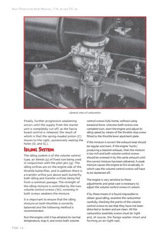
Page 24.Alvis Three Litre Shop Manual - T.A. 21 and T.C. 21General view of carburettorFinally, further progressive weakening occurs until the supply from the starter unit is completely cut off, as the fascia board control is released; the result of which is that the spring-loaded piston (C) moves to the right, successively sealing the holes (O1 and O2 ).Idliingg SSysttemmThe idling system is of the volume control type, air bleeds (u) of fixed size being used in conjunction with the pilot jets (g). The idling orifices are on the engine side of the throttle butterflies, and in addition there is a transfer orifice just above each butterfly, both idling and transfer orifices being fed from a common passage. The strength of the idling mixture is controlled by the two volume control screws (W); screwing in both screws weakens the mixture.It is important to ensure that the idling mixture on both throttles is correctly balanced and the following method is recommended:Run the engine until it has attained its normal temperature, stop it, and screw both volume control screws fully home, without using excessive force. Unscrew both screws one complete turn, start the engine and adjust its idling speed by means of the throttle stop screw fitted to the throttle lever abutment plate.If the mixture is correct the exhaust beat should be regular and even. If the engine %u2018hunts,%u2019 producing a blackish exhaust, then the mixture is too rich and both volume control screws should be screwed in by the same amount until the correct mixture has been obtained. A weak mixture causes the engine to fire erratically, in which case the volume control screws will have to be slackened off.The engine is very sensitive to these adjustments and great care is necessary to adjust the volume control screws in unison.If by these means it is found impossible to obtain good idling, examine the carburettor carefully, checking the points of the volume control screws to see that they have not been distorted or broken and are clean. All the carburettor assembly screws must be tight and, of course, the flange washer intact and forming an air-tight seal.


