


Page 51 - Demo
P. 51
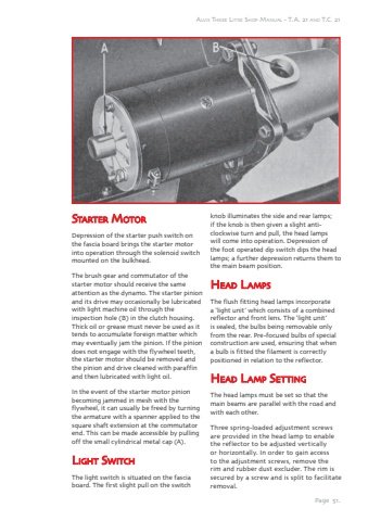
Page 51.Alvis Three Litre Shop Manual - T.A. 21 and T.C. 21SStatartter MottorDepression of the starter push switch on the fascia board brings the starter motor into operation through the solenoid switch mounted on the bulkhead.The brush gear and commutator of the starter motor should receive the same attention as the dynamo. The starter pinion and its drive may occasionally be lubricated with light machine oil through the inspection hole (B) in the clutch housing. Thick oil or grease must never be used as it tends to accumulate foreign matter which may eventually jam the pinion. If the pinion does not engage with the flywheel teeth, the starter motor should be removed and the pinion and drive cleaned with paraffin and then lubricated with light oil.In the event of the starter motor pinion becoming jammed in mesh with the flywheel, it can usually be freed by turning the armature with a spanner applied to the square shaft extension at the commutator end. This can be made accessible by pulling off the small cylindrical metal cap (A).LLigightt SSwitc witchThe light switch is situated on the fascia board. The first slight pull on the switch knob illuminates the side and rear lamps; if the knob is then given a slight anticlockwise turn and pull, the head lamps will come into operation. Depression of the foot operated dip switch dips the head lamps; a further depression returns them to the main beam position.HHeaad LLamp ampsThe flush fitting head lamps incorporate a %u2018light unit%u2019 which consists of a combined reflector and front lens. The %u2018light unit%u2019 is sealed, the bulbs being removable only from the rear. Pre-focused bulbs of special construction are used, ensuring that when a bulb is fitted the filament is correctly positioned in relation to the reflector.HHeaad LLamp amp SSetti ttinggThe head lamps must be set so that the main beams are parallel with the road and with each other.Three spring-loaded adjustment screws are provided in the head lamp to enable the reflector to be adjusted vertically or horizontally. In order to gain access to the adjustment screws, remove the rim and rubber dust excluder. The rim is secured by a screw and is split to facilitate removal.


